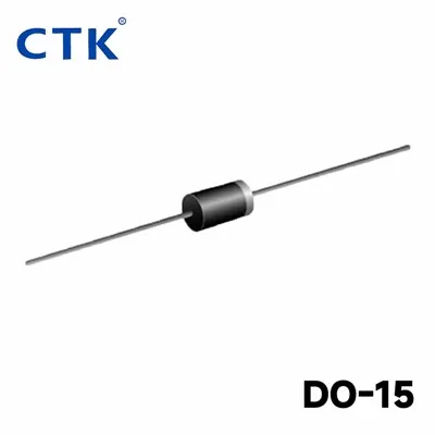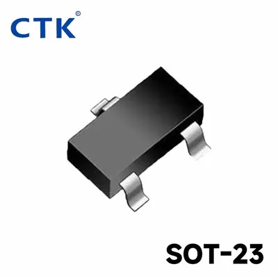






As a trusted supplier of SOT - 23 Plastic Package Low Voltage MOSFETs, I am frequently asked about how to optimize the performance of these MOSFETs in a circuit. In this blog, I will share some essential tips and techniques based on my years of experience in the field.
Understanding SOT - 23 Plastic Package Low Voltage MOSFETs
Before diving into optimization strategies, it's crucial to understand what SOT - 23 Plastic Package Low Voltage MOSFETs are and their typical applications. These MOSFETs come in a small outline transistor (SOT) 23 plastic package, which is compact and suitable for many space - constrained applications. They are designed to operate at low voltages, making them ideal for battery - powered devices, USB charging circuits, and other low - power applications.
If you want to explore our full range of SOT - 23 Plastic Package Low Voltage MOSFETs, please visit our website.
Selecting the Right MOSFET
The first step in optimizing the performance of SOT - 23 Plastic Package Low Voltage MOSFETs in a circuit is to select the right MOSFET for the specific application. Consider the following parameters:
- Voltage Rating: Ensure that the MOSFET's voltage rating is higher than the maximum voltage in the circuit. This will prevent breakdown and ensure reliable operation.
- Current Rating: The MOSFET should be able to handle the maximum current in the circuit without overheating. Overloading the MOSFET can lead to premature failure.
- On - Resistance (RDS(on)): A lower RDS(on) means less power dissipation in the MOSFET, resulting in higher efficiency. In low - voltage applications, even a small reduction in RDS(on) can significantly improve the overall performance.
- Gate - Source Threshold Voltage (VGS(th)): This is the minimum voltage required to turn on the MOSFET. Select a MOSFET with a VGS(th) that is compatible with the drive voltage in your circuit.
Circuit Layout Design
The layout of the circuit can have a significant impact on the performance of SOT - 23 Plastic Package Low Voltage MOSFETs. Here are some layout design tips:
- Minimize Trace Length: Keep the traces connecting the MOSFET to other components as short as possible. This reduces the parasitic inductance and resistance, which can cause voltage drops and ringing.
- Use Adequate Ground Plane: A solid ground plane helps to reduce noise and provides a low - impedance path for the current. Make sure the MOSFET's source terminal is properly connected to the ground plane.
- Separate Power and Signal Traces: To avoid interference, keep the power traces away from the signal traces. This can help prevent noise from affecting the MOSFET's performance.
Thermal Management
Even though SOT - 23 Plastic Package Low Voltage MOSFETs are designed for low - power applications, they still generate some heat. Proper thermal management is essential to ensure the MOSFET operates within its temperature limits.
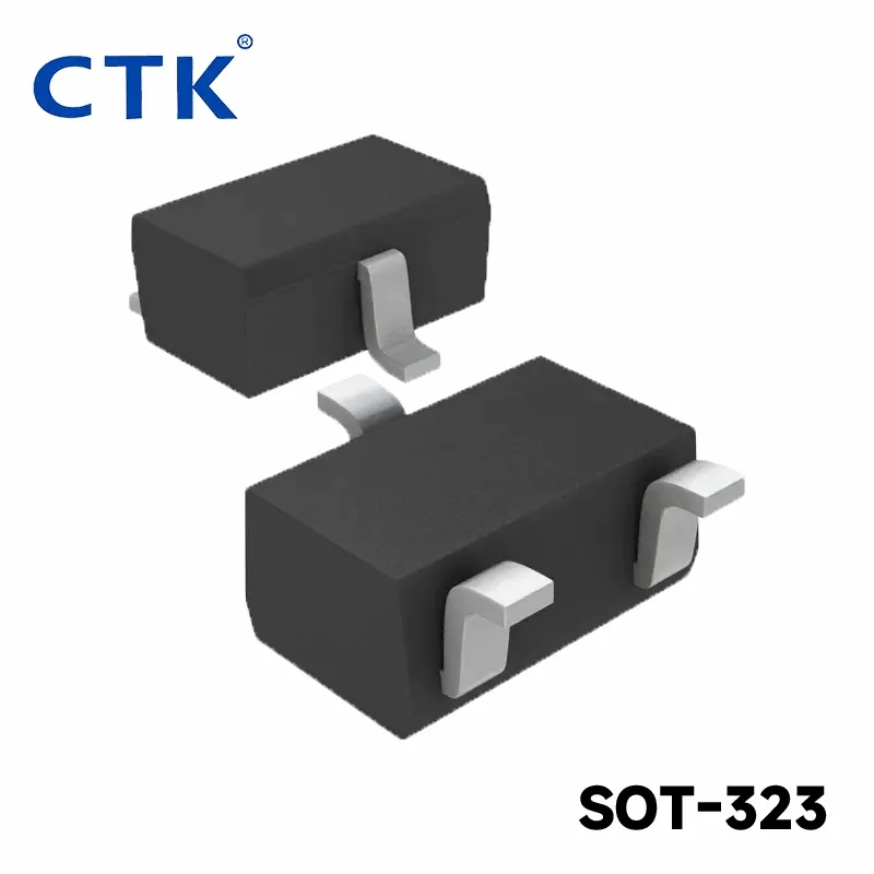
- Heat Dissipation: You can use a heat sink or a PCB with a large copper area to improve heat dissipation. The copper area acts as a heat spreader, transferring the heat away from the MOSFET.
- Avoid Overheating: Do not place the MOSFET too close to other heat - generating components. This can increase the temperature of the MOSFET and reduce its performance and lifespan.
Gate Drive Considerations
The gate drive circuit is responsible for turning the MOSFET on and off. A proper gate drive can significantly improve the performance of the MOSFET.
- Drive Voltage: Ensure that the drive voltage is sufficient to fully turn on the MOSFET. A low drive voltage can result in a high RDS(on), which increases power dissipation.
- Drive Current: The gate drive circuit should be able to provide enough current to charge and discharge the MOSFET's gate capacitance quickly. This reduces the switching time and improves the efficiency of the circuit.
Comparison with Other Package Types
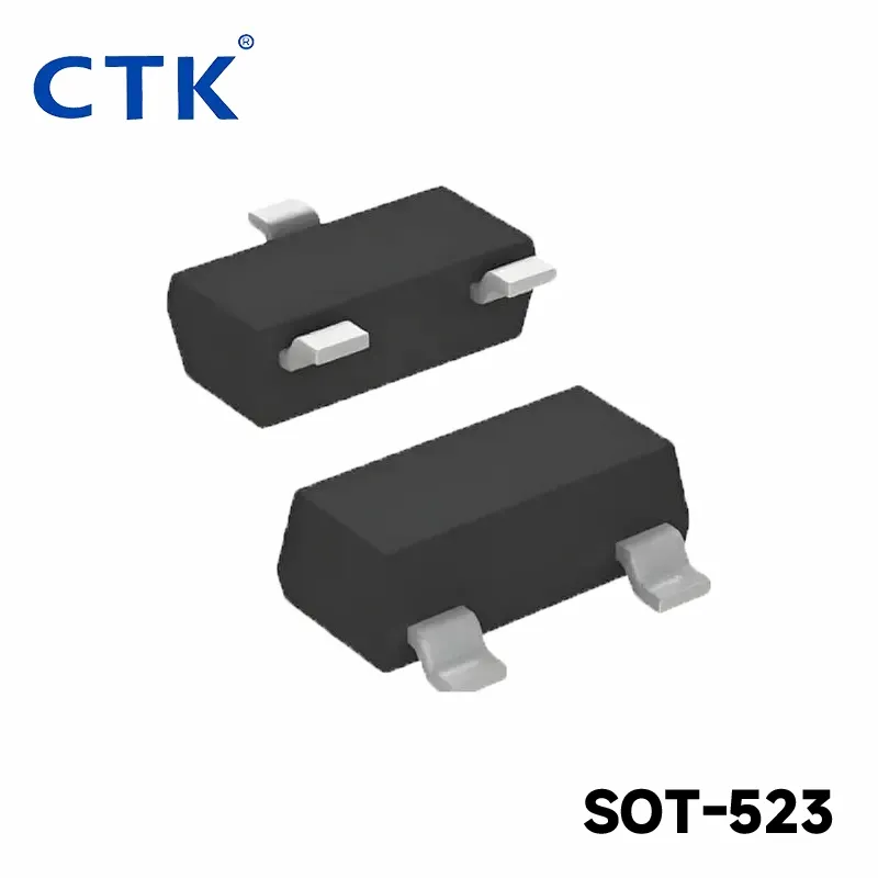
In addition to SOT - 23 Plastic Package Low Voltage MOSFETs, we also offer SOT - 523 Low Voltage MOSFETs and SOT - 323 Low Voltage MOSFETs Plastic Package. Each package type has its own advantages and disadvantages.
- SOT - 523: This package is even smaller than SOT - 23, making it suitable for ultra - compact applications. However, it may have a slightly higher thermal resistance.
- SOT - 323: The SOT - 323 package offers a good balance between size and thermal performance. It is a popular choice for many low - voltage applications.
Testing and Validation
After designing the circuit and selecting the MOSFET, it's important to test and validate the performance. Use appropriate test equipment, such as an oscilloscope, a power analyzer, and a temperature sensor, to measure the MOSFET's performance parameters. Compare the measured results with the expected values and make adjustments if necessary.
Selecting the Right Partner for Your MOSFET Needs
Optimizing the performance of SOT - 23 Plastic Package Low Voltage MOSFETs in a circuit requires careful consideration of various factors, from the selection of the right MOSFET to proper circuit layout, thermal management, and gate drive design. As a reliable supplier, we are committed to providing high - quality MOSFETs and technical support to help you achieve the best performance in your applications.
If you are interested in our SOT - 23 Plastic Package Low Voltage MOSFETs or have any questions about how to optimize their performance in your circuit, please feel free to contact us for a detailed discussion and possible procurement. We look forward to working with you to meet your specific requirements.
References
- Neamen, D. A. (2019). Semiconductor Physics and Devices: Basic Principles. McGraw - Hill Education.
- Baliga, B. J. (2018). Power Semiconductor Devices. Springer.
- Mohan, N., Undeland, T. M., & Robbins, W. P. (2012). Power Electronics: Converters, Applications, and Design. John Wiley & Sons.